an insertion loss of
only 0.062 dB
-3 dB points at
412 and 466 MHz
| + + + - D L 4 X A V - jo 43 xn - h a m b u r g , g e r m a n y , e u r o p e , e a r t h + + + |
| home | rig | sat ant | qsl info | feedback | links | homebrew | H F | V / UHF | disclaimer |
 |
The 432 MHz filter has an insertion loss of only 0.062 dB -3 dB points at 412 and 466 MHz |
| 145 MHz | 220 MHz | 432 MHz | 915 MHz | 1.3 GHz | 2.4 GHz | ||||
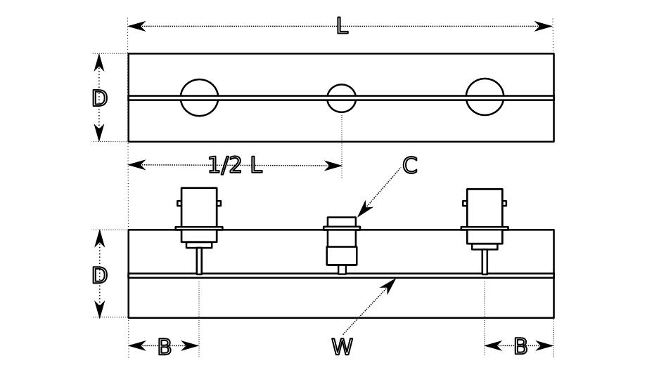
| L | 304.8 | ~230 | 152.4 | 80 | 51 | 25.5 | mm | ||
| L 1/2 | 152.4 | 160 | 76.2 | 40 | 25.5 | 12.7 | mm | ||
| D | >25 | >25 | 25 | 15 | 15 | 10 | mm | ||
| B | 50 | 25.4 | 13.3 | 8.5 | 4.2 | mm | |||
| C | >10 | 1-10 | 1-10 | 1-10 | 1-10 | pF | |||
| W | >2 | >2 | 2 | 2 | 2 | 2 | mm |
435 MHZ L = 150 mm copper D = 15 mm ø B = 25 mm C = ~20 pF ceramic W = 1.8 mm ø Cu/Ag |
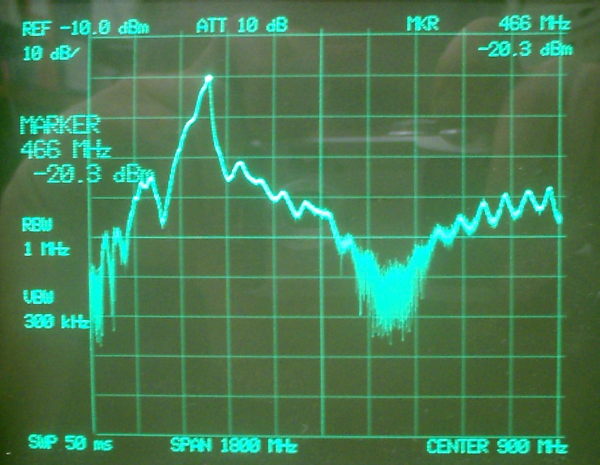 |
plott: the same filter tuned to 466 MHz. insertion loss -1.86 dB. 52 MHz -3 dB bw. tuning range: ~ 350 - 825 MHz. my equipment is poor. the tiny coax was long so the insertion loss will improve a bit. |
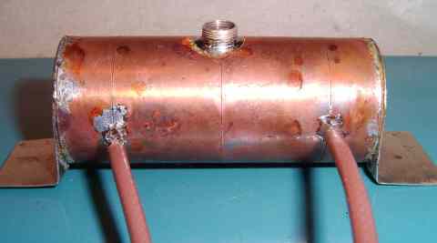 |
1.2 GHZ L = 52 mm copper D = 22 mm ø B = 8.5 mm C = ceramic - see below W = 1.8 mm ø Cu/Ag |
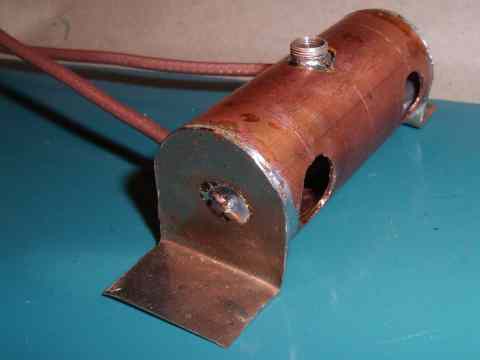 |
the big holes are for soldering coax and trimmer inside the tube. don't forget to drill a third big hole for the trim C. close it with aluminium tape later. all other parts are soldred from the outside. for quality its importand that no solder comes inside the tube. flanges are used for mounting. |
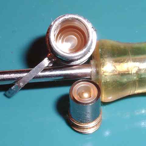 |
the ceramic trimmer used in the 23cm filter (from a 70cm radio). maximum tuning frequency is about 1.3 GHz. |
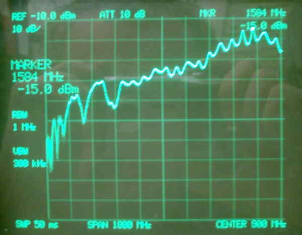 |
the filter tuned to 1584 MHz has a insertion loss of -2 dB with the long tiny Teflon coax. the -3 dB bandwith is 45 MHz. how i build it |
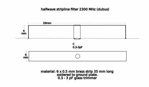 |
this is one strip of a 13cm transverter bandpass (from the DUBUS archive). the stripline is a bit longer and wide, so less C is needed. in and output can be connected like shown above. for best isolation this stripline must be soldred into a shielding box. |
| home | rig | sat ant | qsl info | feedback | links | homebrew | H F | V / UHF | disclaimer |