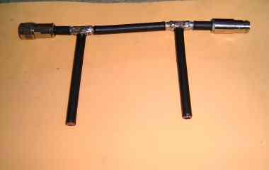
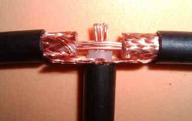
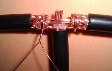
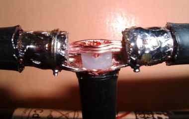
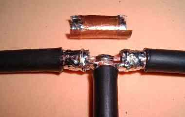
this is the filter.
both stubs are 1/4 lambda * V. the line between the stubs is 1/4 lambda * V. if the stubs are open at the bottom one will have a sharp notch filter for an unwanted frequency (band). if one connect the inner lead and the shield at the bottom of each stub, its a band pass filter for a wide frequency band.
both stubs are 1/4 lambda * V. the line between the stubs is 1/4 lambda * V. if the stubs are open at the bottom one will have a sharp notch filter for an unwanted frequency (band). if one connect the inner lead and the shield at the bottom of each stub, its a band pass filter for a wide frequency band.
a notch filter of this design cuts also Freq.*3, F*5, F*7 ...
(3, 5 , 7 ...* 1/4 lambda).
it has a bandpass characteristic for F*2, F*4, F*6 ...
because the stubs come in 1/2, 1, 1 1/2, ... lambda resonance.
(3, 5 , 7 ...* 1/4 lambda).
it has a bandpass characteristic for F*2, F*4, F*6 ...
because the stubs come in 1/2, 1, 1 1/2, ... lambda resonance.
a bandpass filter (closed at the bottom) let also pass F*3, F*5 F*7 ... and has notch characteristic for F*2, F*4, F*6 ... because the stubs come in 1/2, 1, 1 1/2, ... lambda resonance.
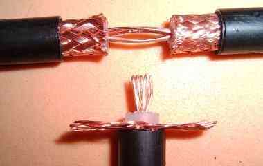
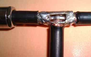
use good coax for your feed line. make the stubs with the same cable type !
you must know the velosety factor " V " of the cable. RG213, as shown here, has V = 0.66 . that means that the stubs are only 66% of 1/4 lambda. other coax cables have different velosety factors.
you must know the velosety factor " V " of the cable. RG213, as shown here, has V = 0.66 . that means that the stubs are only 66% of 1/4 lambda. other coax cables have different velosety factors.
there are several posebilitys to use this filters.
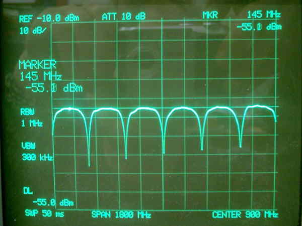
i use this as a notch filter at my 2m sat transmitter to cut off the 3rd harmonic
spur more than 40 dB.
so i have full sensivety with my 70cm sat receivers preamp
so i have full sensivety with my 70cm sat receivers preamp
one single bandpass stub is good to cut static electricity to ground ( if its propper grounded ). that saves the radio frontend and pa.
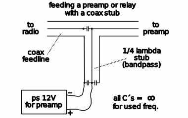
its also possible to feed a preamp via the coax line
the capacitors must handle the transmitter power.
the capacitors must handle the transmitter power.
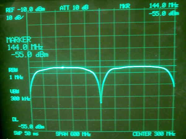
you can NOT use a 2m notch filter stub at the 70cm radio,
it also cuts the 3rd harmonic ( 145 MHz * 3 = 435 MHz ).
most of the signal will be cut off. the receiver will survive but the transmitter will see realy BAD swr.
it also cuts the 3rd harmonic ( 145 MHz * 3 = 435 MHz ).
most of the signal will be cut off. the receiver will survive but the transmitter will see realy BAD swr.